- 2E-Mobility Center
- 3Engineering-Library
- 4Auditorium Tech Stage
- Rail OEM - Serial Production of PowerBriX
- PowerBriX - Launch of Medium Power
- Rail OEM - Introduction
- APU - The Heart of the Train
- Rail Services - Introduction
- PowerBriX - 100% Modular Architecture
- PowerBriX - Interview on Product Strategy
- Welcome to PowerTech City
- PowerTech Converter - A company of smart solutions
- 5Eco-X Space
- 6Exhibition Grounds
1
THE POWERTECH IGBT TEST SYSTEM
THE POWERTECH IGBT TEST SYSTEM
Determination of Energy Loss of Power Semiconductor Modules

An in-house developed semiconductor test system in the R&D Laboratory of PTC Rail OEM GmbH is used to measure switching losses and conduction state losses of various power semiconductor modules
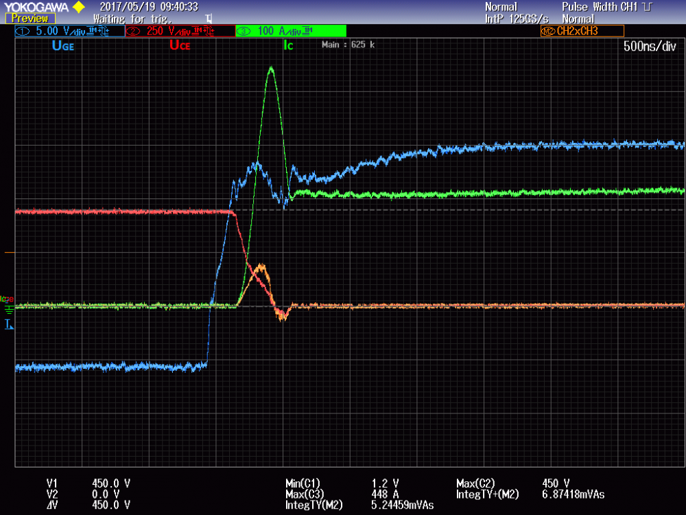
The figure below illustrates the turn on process of an Infineon (R) IGBT module. PowerTech needed a tool for scientific investigation of such modules under dedicated conditions which are unique to our applications. The information provided by the respective manufacturer is often not detailed enough. Manufacturers provide data sheets, which however don't contain standardized technical data. If important technical data is missing or test conditions differ from one manufacturer to the other a drastical limitation of comparable results.
The Test Setup
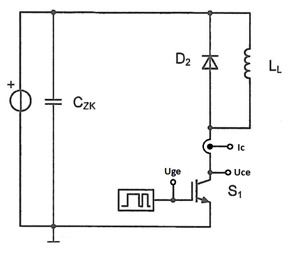
The test setup shows itself in accordance with the standard IEC 60747-9. The setup of the applied test circuit in the below diagram looks quite simple at first glance. However, it is imperatively important to keep parasitic inductances and capacitances in the circuit as low as possible.
The main components of the setup are a direct link capacitor, a module driver with control unit, a load choke, a free-wheeling diode, the test object and measurement equipment such as oscilloscope, differential probe and Rogowski coil.
The double pulse test
In order to determine the switching losses, the “Double Pulse Test” is applied. The semiconductor is turned on twice intermittently, as indicated in the respective figure. The duration of the first pulse determines the current. The duration of the second pulse shall be long enough to switch on the IGBT completely, shortly after which it ends in order to limit the current.
The relevant currents and voltages are illustrated below (idealized):
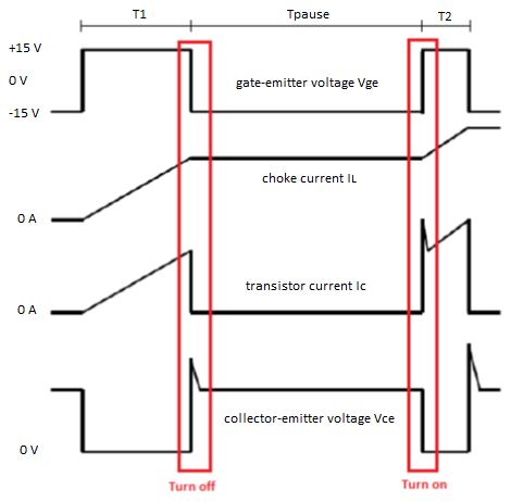
The red areas in this are evaluated, because the current during turn off corresponds with the current during turn on in these areas. This is due to the load choke, which, in view of its stored magnetic energy, keeps the current at an approximately constant level.
In order to calculate the turn on and turn off energy losses the current IC und the voltage VCE are multiplied with each other and integrated over the turn on and turn off time period, as defined in the standard.
Dr. Billy Akpebu, Head of Verification & Validation
Leo Burgthaler, V&V Engineer
PTC Rail OEM GmbH.